Skip to main page content
U.S. flag

An official website of the United States government

Dot gov

The . gov means it’s official. Federal government websites often end in . gov or . mil. Before sharing sensitive information, make sure you’re on a federal government site. VSports app下载.

Https

The site is secure. The https:// ensures that you are connecting to the official website and that any information you provide is encrypted and transmitted securely V体育官网. .

Review
. 2016 Mar;5(2):133-44.
doi: 10.21037/acs.2016.03.14.

V体育ios版 - Uniportal video-assisted thoracic (VATS) lobectomy

Affiliations
Review

Uniportal video-assisted thoracic (VATS) lobectomy

Alan D L Sihoe. Ann Cardiothorac Surg. 2016 Mar.

Abstract

Uniportal video assisted thoracic surgery (VATS) has become one of the most exciting new developments in minimally invasive thoracic surgery in recent years. While the debate over its purported advantages continues, this chapter instead focuses on the technical aspects of performing a lobectomy via the uniportal approach. Using clear medical illustrations to show how each step is performed, the key tips and tricks are laid out for the beginner hoping to learn the technique. VSports手机版.

Keywords: Lobectomy; lung; single port; uniportal; video assisted thoracic surgery (VATS)/thoracoscopic surgery V体育安卓版. .


Conflict of interest statement

Conflicts of Interest: The author (ADLS) is a consultant for Medela AG (Baar, Switzerland).

Figures

Figure 1
Figure 1
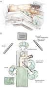
Positioning for uniportal video assisted thoracic surgery (VATS) lobectomy. (A) The patient is placed as for a conventional 3-port VATS procedure in full lateral position with the operating table flexed. The level of flexion should correspond to the site of the uniport to allow maximum natural widening of the intercostal space at that point. The flexion should be enough to allow the shoulder and hip to fall on a horizontal line. In females with wide hips, it is especially important to achieve this horizontal line because otherwise the hip can interfere with camera and instrument movement. Notice that the upper arm is positioned so that the elbow is more cephalad than the shoulder, so that it will not interfere with the surgeon’s movements. The lower arm is flexed at the elbow, and not left extended out beyond the edge of the operating table where it can interfere with the surgeon and assistant’s positioning; (B) the basic positioning of staff and monitors allows for a straight ‘axis’ of surgery from the camera (assistant), through the wound, to the primary video monitor. The surgeon works along this axis and his or her hands approach the wound on either side of the axis. This ensures that the visual and motor axis for the surgeon are the same, facilitating hand-eye co-ordination and reducing ‘fencing’ between the camera and the instruments. When the surgeon and assistant are all looking along the same axis, it is also less likely that the assistant cannot follow the operation or encounter visual problems, such as ‘mirroring’.
Figure 2
Figure 2
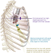
The importance of correct siting the uniport. (A) Correct position (blue): The uniport in the 5th intercostal space allows approaching of the hilar structures at a slight angle, facilitating passage of the stapler in a ‘feet-to-head’ direction across the hilar vessels (see text). At the same time, the left and right hand instruments can approach the hilum via the wound across a relatively wide, comfortable arc; (B) too high (purple): If the uniport is too high, the axis of operation is directly into the hilum. Although dissecting is not a problem, the lack of an angle means that the stapler cannot easily negotiate around the hilar vessels and instead impinges directly on the hilar structures behind; (C) too low (olive): If the uniport is too low, the axis provides a nice angle of approach for the stapler onto the hilar vessels. However, the wound is far away from the hilum, and the arc through which instruments can be inserted via the uniport to reach the hilum becomes greatly narrowed. Bimanual instrumentation to dissect the hilum becomes extremely tricky and can result in considerable ‘fencing’ of instruments.
Figure 3
Figure 3
Communicating with the assistant regarding control of the video-thoracoscope. (A) Standing in front of the patient, the surgeon and assistant’s view of the uniport before them resembles a vertical slit with just enough room for the video-thoracoscope and 2 instruments to be inserted, one above the other. In this ‘traffic light’ configuration, the video-thoracoscope should be kept at the top ‘red light’ position and the left and right hand instruments are inserted at the ‘yellow light’ and ‘green light’ positions. This view keeps the visualization above the level of the instruments on the monitor, in the same way that humans have eyes above the level of the hands. Occasionally, the scope may be relocated to the ‘yellow’ or ‘green light’ positions for specific views. Using this traffic light imagery, the surgeon can verbally communicate exactly where the assistant should be placing the scope in the uniport; (B) proper use of the 30-degree angle of the thoracoscope allows viewing around structures in the chest. Most of the time, the light cable is kept at the 12 o’clock position, allowing a natural ‘top down’ view. To look around a hilar structure, the scope can be moved to the left and the light cable moved to a 9 o’clock position, allow a left-to-right view of the left side of that structure. It can also be moved to the right and the light cable moved to the 3 o’clock position to give a right-to-left view on the right side of the structure. Using this clock face imagery, the surgeon can verbally communicate exactly what 30-degree angulation is required from the assistant.
Figure 4
Figure 4
Dissection of the RUL pulmonary vein. The lung is retracted laterally, displaying the RUL pulmonary vein running vertically down from the RUL on the monitor (with the mediastinum as the horizontal ‘floor’). Long Metzenbaum scissors are used to open the pleura over the vein and dissect onto the subadventitial layer. The vein from the RML is clearly seen on the left and is preserved. (A) Blunt dissection using a Yankauer sucker or (in this case) a ‘peanut’ pledget mounted on a curved instrument allows gentle dissection around and behind the vein. A curved Rumel forceps is used to get around the back of the vein. It is then used to open up the space behind by gentle opening and closing. It is finally used to grasp a silk thread to loop around the vein, facilitating subsequent passage of the stapler; (B) the stapler is inserted directly towards the vein, with the thinner anvil engaging the left (feet) side of the vein. Notice that if the stapler were advanced further in this direction it would be forced to stop as it impinges on all the hilar structures behind the vein; (C) with the anvil engaged on the left of the vein, the lung is retracted cephalad and forwards. This widens up the space behind the vein. Simultaneously, the reticulated stapler is also rotated clockwise. The head of the stapler is parallel to the horizontal ‘floor’. In this angulation, the anvil can be advanced in a left-to-right (feet-to-head) direction, and it will emerge from behind the right side of the vein no longer impinging on anything. After the vein is divided, using the original lateral retraction of the RUL, the pulmonary artery can now be seen clearly behind where the vein once ran.
Figure 5
Figure 5
Dissection of the right upper lobe (RUL) pulmonary artery truncus. The lung is retracted laterally, displaying the RUL pulmonary artery truncus running vertically up to the RUL on the monitor (see Figure 4). Long Metzenbaum scissors are used to dissect around the truncus onto the subadventitial layer. Blunt dissection using a Yankauer sucker allows further gentle dissection around and behind the artery. A curved Rumel forceps is used to get around the back of the artery. It is then used to open up the space behind by gentle opening and closing, facilitating subsequent passage of the stapler. The stapler is inserted directly towards the artery, with the thinner anvil engaging the left (feet) side of the vessel. Notice that if the stapler were advanced further in this direction it would be forced to stop as it impinges on the RUL bronchus behind the artery. (A) With the anvil engaged on the left of the artery, the lung is retracted slightly cephalad and forwards. This widens up the space behind the artery. Simultaneously, the reticulated stapler is also rotated clockwise very subtly. In this angulation, the anvil can be advanced in an anterior-to-posterior and slight left-to-right (feet-to-head) direction, and it will emerge from behind the right side of the artery no longer impinging on anything; (B) after the artery is divided, using the original lateral retraction of the RUL, the RUL bronchus can now be seen clearly behind where the artery once ran. Notice the black lymph node on the left (feet) side of the RUL bronchus, which is a constant landmark indicating a safe point of entry for dissection of the bronchus.
Figure 6
Figure 6
Dissection of the right upper lobe (RUL) bronchus. (A) The lymph node on the left (feet) side of the RUL bronchus is dissected and removed. Removal of that lymph node exposes the site where a Roberts or Rumel forceps can be safely inserted to dissect around the RUL bronchus in an anterior-to-posterior and slight left-to-right (feet-to-head) direction; (B) the stapler is introduced in the same anterior-to-posterior and slight left-to-right (feet-to-head) direction. At this point, this direction is virtually straight in from the uniport, and roticulating staplers and curved tip reloads are usually unnecessary.
Figure 7
Figure 7
Dissection of the right upper lobe (RUL) pulmonary artery ascending branch. After division of the RUL bronchus, further ‘opening of the book’ by continuing to retract the RUL laterally exposes the small RUL pulmonary artery ascending branch. This is seen arising from the interlobar pulmonary artery up towards the RUL. Long Metzenbaum scissors are used to gently dissect around this vessel. Passage of a wide stapler across such a small vessel incurs a risk of avulsion or tearing. (A) Often using a polymer vascular ligating clip—with its finer introducer—may be a more appropriate to secure the artery branch. The ascending artery branch is double-clipped proximally; (B) it can then be divided distally using an energy device (in this case an ultrasonic dissector-divider) to simultaneously seal and cut.
Figure 8
Figure 8
Completing the interlobar fissure using staple-division (in a ‘fissureless’ strategy). The stapler is inserted from the uniport to grasp along the fissure in an anterior-to-posterior direction. This view of the lateral side of the right lung shows the stapler ideally sited right along the fissure between the right upper lobe (RUL) and Right middle lobe (RML) without overtly veering into either lobe. It is important to view the medial aspect of the staple line before firing. The lung is retracted towards the feet end and laterally, and it must be checked that the stapler has not been placed across the important structures (the RML pulmonary vein and the interlobar pulmonary artery) before firing. After firing, the RUL and RML should be seen to be separated and the staple lines on either side intact. The interlobar pulmonary artery is left fully intact, and the polymer vascular clips used on the posterior ascending artery branches should have been well avoided by the staple line. The remaining posterior fissure is similarly staple-divided to complete the lobectomy.
Figure 9
Figure 9
Delivery of the resected lobe. A sterilized zip-lock bag is inserted into the chest. The zip-lock rib around the mouth of the bag allows it to naturally spring open inside the chest. (A) One ring forceps is used to hold the mouth of the bag, while another is used to grasp the resected lobe and feed it into the bag; (B) the zip-lock mouth of the bag is first delivered out of the wound. The resected lobe is then directly pulled out from within the bag. The intact base of the bag prevents spillage of tumor contents into the pleural space as the lobe is squeezed through the small uniport.
Figure 10
Figure 10
Chest drain placement and wound closure. A chest tube (in this case 24F in size) is placed at one end of the uniport and anchored with a silk suture. Notice that a long full-thickness silk suture (long black thread) has been placed already across the position of the chest tube: this is used to close the wound at the time of chest tube removal. The rest of the uniport wound is closed in layers. The deep layers of the wound should be meticulously and securely sutured. However, the outermost skin closure should not be made too tight around the chest tube. This is to minimize the risk of skin necrosis around the chest tube which can lead to further wound complications.

References

    1. Sihoe AD, Yim AP. Video-assisted pulmonary resections. In: Pearson's Thoracic and Esophageal Surgery, Third Edition. Patterson GA, Cooper JD, Deslauriers J, et al. (Eds). Philadelphia: Elsevier.2008:970-88.
    1. Sihoe AD, Yim APC. VATS as a diagnostic tool. In: General Thoracic Surgery (7th Edition). Shields TW, Locicero J, Ponn RB, (Eds). Philadelphia:Lippincott Williams & Wilkins.2009:313-32.
    1. Fernando HC, Landreneau RJ, Mandrekar SJ, et al. Analysis of longitudinal quality-of-life data in high-risk operable patients with lung cancer: results from the ACOSOG Z4032 (Alliance) multicenter randomized trial. J Thorac Cardiovasc Surg 2015;149:718-25; discussion 725-6. 10.1016/j.jtcvs.2014.11.003 - DOI (V体育官网) - PMC - PubMed
    1. Sihoe AD. The Evolution of VATS Lobectomy. In: Cardoso P. eds. Topics in Thoracic Surgery. Rijeka: Intech, 2011:181-210.
    1. Sihoe AD. The evolution of minimally invasive thoracic surgery: implications for the practice of uniportal thoracoscopic surgery. J Thorac Dis 2014;6:S604-17. - PMC - PubMed

Publication types

"V体育官网入口" LinkOut - more resources