<b draggable="3Z0p0vWX"><bdo draggable="MAuKzWm"></bdo></b><area dropzone="K94vJCkx"></area> Skip to main page content
U.S. flag

An official website of the United States government

Dot gov

The VSports app下载. gov means it’s official. Federal government websites often end in . gov or . mil. Before sharing sensitive information, make sure you’re on a federal government site. .

Https

The site is secure. The https:// ensures that you are connecting to the official website and that any information you provide is encrypted and transmitted securely V体育官网. .

. 2014 Jun 1;111(11):2374-91.
doi: 10.1152/jn.00804.2013. Epub 2014 Mar 5.

Lag structure in resting-state fMRI

Affiliations

Lag structure in resting-state fMRI

A Mitra et al. J Neurophysiol. .

"V体育ios版" Abstract

The discovery that spontaneous fluctuations in blood oxygen level-dependent (BOLD) signals contain information about the functional organization of the brain has caused a paradigm shift in neuroimaging. It is now well established that intrinsic brain activity is organized into spatially segregated resting-state networks (RSNs). Less is known regarding how spatially segregated networks are integrated by the propagation of intrinsic activity over time. To explore this question, we examined the latency structure of spontaneous fluctuations in the fMRI BOLD signal. Our data reveal that intrinsic activity propagates through and across networks on a timescale of ∼1 s. Variations in the latency structure of this activity resulting from sensory state manipulation (eyes open vs VSports手机版. closed), antecedent motor task (button press) performance, and time of day (morning vs. evening) suggest that BOLD signal lags reflect neuronal processes rather than hemodynamic delay. Our results emphasize the importance of the temporal structure of the brain's spontaneous activity. .

Keywords: dynamics; fMRI; functional connectivity; resting state V体育安卓版. .


Figures

Fig. 1.
Fig. 1.
Calculation of pairwise time series lag using cross-covariance and parabolic interpolation. Top: 195 s of 2 sampled time series extracted from 2 loci in the brain. Bottom left: the corresponding lagged cross-covariance function, computed over a full run (∼300 s) (Eq. 2). The lagged cross-covariance is defined over the range ±L, where L is the run duration. The range of the plotted values is restricted to ±12 s, which is equivalent to ±4 frames (red markers) when the repetition time is 3 s. The lag between the time series is the value at which the [absolute value of the] cross-covariance function is maximal. This extremum can be determined at a resolution finer than the temporal sampling density (1 frame every 3 s) by performing parabolic interpolation (green line, bottom right) through the computed values (red markers). This extremum (arrow, yellow marker) defines both the lag between time series i and ji,j; Eq. 4) and the corresponding amplitude (ai,j; Eq. 5).
Fig. 2.
Fig. 2.
Results obtained in data set 1. The 692 subjects were randomly divided into 7 equally sized subgroups of ∼99 subjects each. A: latency projection of the time-delay (TD) result obtained in the first subgroup illustrated in voxel-space. Lag is measured in seconds. B: latency projection of the amplitude-weighted time-delay (AWTD) result corresponding to the TD result shown in A. Because the blood oxygen level-dependent (BOLD) signal magnitude depends on multiple fMRI sequence parameters, the unit of amplitude-weighted lag is arbitrary. C: surface representation of the volumetric result shown in A. Arrows point to specific regions mentioned in discussion: posterior precuneus cortex (PCC), ventromedial prefrontal cortex (VMPFC), dorsal anterior cingulate cortex (dACC), anterior insula (AI), posterior parietal cortex (PPC), and dorsolateral prefrontal cortex (DLPFC). D: spatial correlation between all TD (first 7 rows/columns) and AWTD (last 7 rows/columns) latency projections calculated in the 7 subgroups.
Fig. 3.
Fig. 3.
A: latency process amplitude (LPA) map illustrated in voxel-space obtained in the first subgroup of data set 1 (same data as in Fig. 2, A–C). The scale is in units of BOLD amplitude. See Eq. 8 for derivation. B: surface representation of the volumetric result shown in A. C: spatial correlation between all amplitude maps calculated in the 7 subgroups of data set 1.
Fig. 4.
Fig. 4.
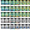
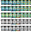
Latency results obtained in data set 2. A: eyes open (EO). B: eyes closed (EC). C: EO minus EC. D: voxels with a statistically significant EO vs. EC latency effect. E: EO minus EC LPA difference image. Color indicates statistically significant voxels.
Fig. 5.
Fig. 5.
Latency results obtained in data set 3. A: before button-press task. B: after button-press task. C: after minus before. D: voxels with a statistically significant recent task performance latency effect. E: after minus before LPA difference image. Color indicates statistically significant voxels.
Fig. 6.
Fig. 6.
Latency results obtained in data set 4. A: morning latency map. B: evening latency map. C: evening minus morning change in latency. Warm hues indicate increased lateness in the evening. Cool hues indicate increased earliness in the evening. D: statistically significant latency differences are seen in entorhinal and insular cortex. E: previously reported (Shannon et al. 2013) diurnal change in functional connectivity. Magenta indicates the 2 regions of interest, right and left entorhinal cortex, exhibiting the greatest diurnal change in functional connectivity with the rest of the brain (circled in central slices in A–E). Presently reported diurnal changes in latency (A–D) correspond to previously published functional connectivity changes in entorhinal cortex (E).
Fig. 7.
Fig. 7.
Real and surrogate resting-state networks (RSNs). RSN labels and color codes are presented at bottom left. To test the statistical significance of the latency-RSN relationship, we created surrogate RSNs matched in spatial frequency to real RSNs. The real RSNs were defined as the group-level winner-take-all result in Hacker et al. (2013) (referred to here as “MLP RSNs”). Surrogate RSNs (n = 1,000) were generated by applying symmetric group operations to the real RSNs (see appendix). One typical example of surrogate RSNs is illustrated adjacent to the real RSNs. Spatial frequency domain representations (3D Fourier transforms of RSNs and surrogate RSNs) are at top right. The spatial frequency domain results are averaged over all real RSNs and over all surrogate RSNs, respectively, omitting the cerebrospinal fluid (CSF) component. Only the fz = 0 planes of the 3D spatial frequency domain representations are shown. The graph (bottom right) shows relative spectral power (in dB) read out along the diagonal blue traces in the frequency domain representations. The plots are symmetric about the Nyquist folding frequency = 0.53 mm, which reflects the spatial sampling density (3-mm cubic voxels). Critically, the spatial frequency content of the surrogate RSNs is well matched to the real RSNs.
Fig. 8.
Fig. 8.
Histogram of summed squared mean latency values in surrogate RSNs. One thousand surrogate RSN partitions (e.g., Fig. 7) were generated. The latency mean was evaluated for each surrogate RSN. On the assumption that mean RSN latencies are normally distributed about zero, the sum of squares of these values theoretically is distributed as χ2(7). The light blue trace represents the theoretical gamma probability density function fit to the simulations (blue histogram). The vertical pink line represents the summed squared latency values in the real RSNs (0.006 s2). A squared sum value of 0.006 s2 corresponds to a root mean square value of 0.03 s, as reported in the text. The surrogate data indicate that the probability of this outcome occurring by chance is P < 0.0096.
Fig. 9.
Fig. 9.
Relationship of latency to RSNs. Figure shows a TD matrix with regions of interest (ROIs) ordered by RSN membership (see Fig. 7 for abbreviations). Within each RSN, the ROIs are further ordered by latency. Note wide range of latencies within RSNs (diagonal blocks, each necessarily anti-symmetric) and anti-symmetric features across RSNs (off-diagonal blocks). Note also absence of organization in CSF blocks. Blocks referred to in the main text are outlined in white. The diagonal blocks in the TD matrix illustrate that each network has early, middle, and late components. Moreover, the off-diagonal blocks have early, middle, and late components. Therefore, no network leads or follows any other network. Rather, lags are equivalently distributed within and across RSNs.
Fig. 10.
Fig. 10.
AWTD matrix corresponding to Fig. 9. Blocks referred to in the main text are outlined in white.
Fig. 11.
Fig. 11.
Comparison of cerebral blood flow (CBF) vs. TD latency projection. A: CBF map obtained in a group of 33 normal young adults. B: TD latency projection; same data as Fig. 2, A–C. C: scatterplot showing the relationship between CBF and the latency projection. Each dot represents 1 ROI. To test whether the reproducibility of latency structure (Fig. 2D) is attributable to CBF, we computed the mean cross-group correlation for the 7 cohorts in data set 1, before and after regressing out the effects of CBF. The mean cross-group correlation was r = 0.898 in both cases. This result demonstrates that the effect of CBF on measured latency, if present, is negligible.
Fig. 12.
Fig. 12.
Venous contribution to latency structure. A: venogram. B: TD latency projection for comparison. Our gray matter masking procedure (see imaging methods) excludes many of the voxels that correspond to venous structures, but some overlap is apparent. C: TD latency projection with venous structures masked out.
Fig. 13.
Fig. 13.
Estimation of TD matrix model order. The TD matrix intrinsic dimensionality likelihood was calculated (Minka 2001) with the Bayesian information criterion (BIC) in the 7 groups corresponding to Fig. 2. In each group, the dimensionality of highest likelihood is 2. This result implies the existence of 2 transitive systems of lags within the TD matrix. Regionally dependent neurovascular coupling can explain only 1 of these transitive systems of lags. Therefore, hemodynamic delays, even if they are substantial, cannot account for the entirety of latency structure.

References

    1. Allison M, Bodine E, DeAlba LM, Debnath J, DeLoss L, Garnett C, Grout J, Hogben L, Im B, Kim H, Nair R, Pryporova O, Savage K, Shader B, Wehe AW. Minimum rank of skew-symmetric matrices described by a graph. Linear Algebra Appl 432: 2457–2472, 2010
    1. Amemiya S, Kunimatsu A, Saito N, Ohtomo K. Cerebral hemodynamic impairment: assessment with resting-state functional MR imaging. Radiology 270: 548–555, 2014 - PubMed
    1. Axmacher N, Draguhn A, Elger CE, Fell J. Memory processes during sleep: beyond the standard consolidation theory. Cell Mol Life Sci 66: 2285–2297, 2009 - "VSports手机版" PMC - PubMed
    1. Beckmann CF, DeLuca M, Devlin JT, Smith SM. Investigations into resting-state connectivity using independent component analysis. Philos Trans R Soc Lond B Biol Sci 360: 1001–1013, 2005 - PMC - PubMed
    1. Bianciardi M, Fukunaga M, van Gelderen P, Horovitz SG, de Zwart JA, Duyn JH. Modulation of spontaneous fMRI activity in human visual cortex by behavioral state. Neuroimage 45: 160–168, 2009 - PMC - PubMed

MeSH terms