Skip to main page content
U.S. flag

An official website of the United States government

Dot gov

The . gov means it’s official. Federal government websites often end in . gov or . mil. Before sharing sensitive information, make sure you’re on a federal government site. VSports app下载.

Https

The site is secure. The https:// ensures that you are connecting to the official website and that any information you provide is encrypted and transmitted securely. V体育官网.

. 2010 Jun 15:11:323.
doi: 10.1186/1471-2105-11-323.

A boundary delimitation algorithm to approximate cell soma volumes of bipolar cells from topographical data obtained by scanning probe microscopy (V体育安卓版)

Affiliations

A boundary delimitation algorithm to approximate cell soma volumes of bipolar cells from topographical data obtained by scanning probe microscopy

V体育2025版 - Patrick Happel et al. BMC Bioinformatics. .

Abstract

Background: Cell volume determination plays a pivotal role in the investigation of the biophysical mechanisms underlying various cellular processes. Whereas light microscopy in principle enables one to obtain three dimensional data, the reconstruction of cell volume from z-stacks is a time consuming procedure. Thus, three dimensional topographic representations of cells are easier to obtain by scanning probe microscopical measurements VSports手机版. .

Results: We present a method of separating the cell soma volume of bipolar cells in adherent cell cultures from the contributions of the cell processes from data obtained by scanning ion conductance microscopy. Soma volume changes between successive scans obtained from the same cell can then be computed even if the cell is changing its position within the observed area. We demonstrate that the estimation of the cell volume on the basis of the width and the length of a cell may lead to erroneous determination of cell volume changes. V体育安卓版.

Conclusions: We provide a new algorithm to repeatedly determine single cell soma volume and thus to quantify cell volume changes during cell movements occuring over a time range of hours. V体育ios版.


Figures
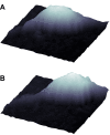
Figure 1
Figure 1
An oligodendrocyte precursor cell undergoing temporal changes in position within the observed scanning frame. A and B: Scanning ion conductance microscopic images of the same cell obtained at t = 0 minutes and t = 10 minutes. Note the change in position of the cell body. Due to the dislocation of the cell soma the two scans include variable amounts of the processes extending from the soma. To obtain a quantification of the cell soma volume, an algorithm was developed to separate the soma from the processes.
Figure 2
Figure 2
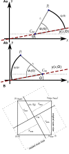
Principles of the approximation procedure to determine the basal soma area. A: The heading direction of the bipolar cell within the observed area is estimated, indicated by the arc. B: The cell is rotated around its highest part (represented by C90 as defined in the text, see also Figure 3) by its heading direction to position the cell parallel to the abscissa. The cell is divided into its frontal and its rear part at the level of C90. Each part of the cell is investigated linewise as indicated by the dashed lines in B. C: Side view (emphasized by the yellow box) of a single line. The contour of the cell at a single line is approximated by fitting a polynomial to the cell. The root of the polynomial (red dot in C) yields the boundary of the cell soma for the particular line. D depicts the result of the approximation procedure: The roots (red dots) obtained from fitting every single line of the frontal and rear part of the cell approximate the boundary of the cell soma.
Figure 3
Figure 3
Representation of the location of the nucleus by C90. A and B show light microscopic images from an oligodendrocyte precursor cell whose nucleus was stained using Hoechst 33342 (B) and that was scanned by backstep SICM (C). The position of the scan is depicted in A and a three dimensional representation of the data obtained by SICM is shown in C. The positions of CT for varying T (between 10% and 90% of the maximal z-value) calculated from the SICM data with respect to the position of the centroid of the stained area (obtained from fluorescence microscopy as shown in B, marked by the red cross-hair) are drawn rotated and magnified in D (blue dots and blue cross, labels indicate T in percent). E shows the average distances between CT and the centroid of the staining of the nucleus obtained from 3 different determinations, error bars indicate ± SD.
Figure 4
Figure 4
Overview of the various lengths, angles and points. A: The angle Θ defines the direction of a straight line y (x, Θ) through C90. The angle ϕi (Θ) originates at C90 and is defined as the smallest angle between the line ri from C90 to the pixel Pi and y (x, Θ). Aa and Ab illustrate the relation for Pi located at opposite sides of C90. si(ϕ) is defined as the arc of the circle with radius ri from y (x; Θ) to Pi . B: The dimensions of the translated and rotated scan data based on the distances (dotted lines) of the vertices of the original scan to the straight lines through C90 in and perpendicular to the heading direction of the cell (straight lines). Note the increase in basal area caused by the rotation (see also Figure 11 and Figure 12).
Figure 5
Figure 5
Interpolation of rotated and translated data. A: The original data set. B: A magnification of one pixel formula image of the rotated data and its surrounding four projections of the original data, formula image to formula image The triangles Mk consisting of three of the projections formula image are indicated by the dotted lines. D: The rotated data set with C90 located in the origin. C: The sum ζk of the three angles at formula image to the three points of a triangle is 2π.
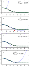
Figure 6
Figure 6
Characteristic contours of the soma of OPCs. A: Contour of a cell soma approximating a circular shape. The black line marks the level of C90. The dashed gray line indicates a parabola fitted to the cell contour that traces the soma but crops the process. B: Contour of a cell soma protruding into the direction of a process. A parabola (gray dashed line) would crop the protrusion of the soma whereas a polynomial of third degree includes the protrusion but still crops the process.
Figure 7
Figure 7
Example of the fitting procedure. A-D show the approximated polynomials F y' (r) (blue lines) for r = 4; 5; 9 and 14, respectively. Neither Fy'(r = 4) nor Fy'(r = 14) (panels A and D) had a corresponding Xy' (r) and thus were not taken into consideration. Both Fy' (r = 8) and Fy'(r = 9) (panels B and C) had a corresponding Xy' (r); thus the corresponding formula image were compared. Since formula imageXy' (r = 8) (red arrow-head in B) was selected as the boundary of the cell soma for the investigated y'.
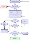
Figure 8
Figure 8
Flow-chart of the procedure to find the best fit. The procedure investigates the approximations to an increasing number of data points and selects the one with a positive, non-complex root and the best corresponding formula image Note that the chart omits some additional tests (see text) to ensure an error free operation as indicated by the dotted arrow in the lower right part. Note that NaN ≡ not a number.
Figure 9
Figure 9
Application of boundary delimitation algorithm to simulated objects. A-C: Half-ellipsoids with the corresponding radii rx = ry = r0 (A), rx = 1.25 r0; ry = 0.8 r0 (B) and rx = 0.8 r0; ry = 1.25 r0 (C). The radius in z-direction is rz = r0. D-F: Hemisphere/half-ellipsoids from A-C with additional extensions. G: Normalized volume (Vn) computed by the boundary delimitation algorithm (BDA) as well as by thresholding simulating a half-ellipsoid with the radii rx = t r0 and rz = 1/t r0 for 1 ≤ t ≤ 2 and Δt = 0.05. Corresponding thresholds were 0.4 rz and 0.4 r0, respectively. H: Volumes of the objects from D-F computed by the BDA (blue) and by thresholding (red) using a threshold of 0.4 rz. Gray boxes indicate erroneously determined changes in volume when the shape of the object changes as indicated by the respective arrows. I: The addition of the extensions changes the volume of the simulated cell soma with respect to the mere half ellipsoid as indicated by the red area.
Figure 10
Figure 10
Simulating objects with varying geometrical parameters. A shows the volume normalized to the corresponding Vsum determined by the boundary delimitation algorithm (BDA, blue crosses) and via thresholding (red dots) when simulating the height of the processes as h rz with Δh = 0.01. The stepwise decrease vanishes when the resolution increases (red cross-hairs). B shows the impact of the width of the processes by simulating their widths as w 2 ry . Note that only the results for the BDA are shown. C and D show the volume normalized to the corresponding Vsum when simulating objects with changing the processes' height (as in A) and the radii of the half-ellipsoid as rx = ry = t1/2 r0 and rz = 1/t r0. The color coded area in the bottom indicates Vn corresponding to the color bar plotted between C and D. C shows the results for the BDA, D for thresholding. The corresponding steps of the parameters were Δh = 0.01 and Δt = 0.05.
Figure 11
Figure 11
Application of the boundary delimitation algorithm to live cells. A: Top views of the original data of four different OPCs obtained by pulse-mode SICM in floating backstep configuration. Orange lines indicate y (x, θh), blue dots indicate C90. B: Top views of the rotated, translated and interpolated data from the corresponding scans from A. The height of each scan and its corresponding rotated data is indicated by the color bars in A. C: Approximated soma area of the corresponding scans. The contribution of each pixel to the entire soma volume is indicated by the color bars at the bottom of each panel.
Figure 12
Figure 12
Shape and volume dynamics of the soma of a migrating cell. A and B show three dimensional representations of successive SICM recordings at a time interval of 11 min and the corresponding boundary delimitation approximations of the cell soma. Color bars indicate height and the contribution to the entire soma volume per pixel, respectively. C shows the corresponding widths, lengths and heights of the cell soma. Whereas the width remained constant, the length decreased and the height increased. D shows the corresponding soma volumes, subdivided into frontal and rear part with respect to the direction of migration at the level of C90. Note the swelling of about 140 pL. E shows the size of the area covered by the cell soma. Note that in contrast to the cell soma volume, the area covered by the soma slightly decreased. F shows the ratios of the determined geometrical parameters illustrating their changes between the two scans.

"VSports app下载" References

    1. Lang F, Ritter M, Völkl H, Häussinger D. The biological significance of cell volume. Ren Physiol Biochem. 1993;11(12):48–65. - PubMed
    1. Wehner F, Olsen H, Tinel H, Kinne-Saffran E, Kinne RKH. Cell volume regulation: osmolytes, osmolyte transport, and signal transduction. Rev Physiol Biochem Pharmacol. 2003;11:1–80. full_text. - "V体育官网入口" PubMed
    1. Dietzel I, Heinemann U, Hofmeier G, Lux HD. Transient changes in the size of the extracellular space in the sensorimotor cortex of cats in relation to stimulus-induced changes in potassium concentration. Exp Brain Res. 1980;11(4):432–9. doi: 10.1007/BF00236151. - DOI - PubMed
    1. Dietzel I, Heinemann U, Lux HD. Relations between slow extracellular potential changes, glial potassium buffering, and electrolyte and cellular volume changes during neuronal hyperactivity in cat brain. Glia. 1989;11:25–44. doi: 10.1002/glia.440020104. - DOI - PubMed
    1. Hall SK, Zhang J, Lieberman M. An early transient current is associated with hyposmotic swelling and volume regulation in embryonic chick cardiac myocytes. Exp Physiol. 1997;11:43–54. - "VSports" PubMed

V体育官网 - Publication types